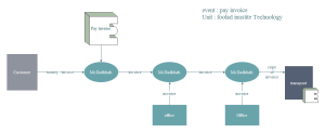
Flow of Event

An event flow diagram is a kind of diagram that is used to document the flow of events. The event flowdiagram consists of event rule groups and business steps. With an event flow diagram, complex eventrelationship and related events are visually displayed to people.

Event Flow Diagram Examples

Comments

Popular posts from this blog

Activity Diagram

What is an Activity Diagram? An activity diagram visually presents a series of actions or flow of control in a system similar to a  flowchart  or a  data flow diagram . Activity diagrams are often used in business process modeling. They can also describe the steps in a  use case diagram . Activities modeled can be sequential and concurrent. In both cases an activity diagram will have a beginning and an Basic Activity Diagram Notations and Symbols Initial State or Start Point A small filled circle followed by an arrow represents the initial action state or the start point for any activity diagram. For activity diagram using swimlanes, make sure the start point is placed in the top left corner of the first column. Activity or Action State An action state represents the non-interruptible action of objects. You can draw an action state in SmartDraw using a rectangle with rounded corners. Action Flow Action flows, also called edges and paths, illustrat...

UML Communication Diagrams Overview

Communication diagram  (called  collaboration diagram  in UML 1.x) is a kind of UML  interaction diagram  which shows interactions between objects and/or  parts  (represented as  lifelines ) using sequenced messages in a free-form arrangement. Communication diagram  corresponds (i.e. could be converted to/from or replaced by) to a simple  sequence diagram  without structuring mechanisms such as interaction uses and combined fragments. It is also assumed that  message overtaking  (i.e., the order of the receptions are different from the order of sending of a given set of messages) will not take place or is irrelevant. The following nodes and edges are drawn in a UML communication diagrams:  frame ,  lifeline ,  message . These major elements of the communication diagram are shown on the picture below. The major elements of UML communication diagram. Frame Communication diagrams could be shown wit...

Use Case

Dalam rekayasa perangkat lunak dan sistem, use case adalah daftar tindakan atau langkah-langkah acara yang biasanya mendefinisikan interaksi antara peran (dikenal dengan Unified Modeling Language sebagai aktor) dan sebuah sistem untuk mencapai suatu tujuan. Aktor tersebut bisa menjadi manusia atau sistem eksternal lainnya. Dalam kasus penggunaan teknik sistem digunakan pada tingkat yang lebih tinggi daripada rekayasa perangkat lunak yang sering mewakili misi atau tujuan pemangku kepentingan. Persyaratan rinci kemudian dapat ditangkap dalam Sistem Pemodelan Bahasa (SysML) atau sebagai laporan kontraktual. Analisis kasus penggunaan merupakan teknik analisis persyaratan penting dan berharga yang telah banyak digunakan dalam rekayasa perangkat lunak modern sejak diperkenalkan secara formal oleh Ivar Jacobson pada tahun 1992. Pengembangan use case driven adalah karakteristik utama dari banyak model dan kerangka proses seperti ICONIX, Unified Proses (UP), IBM Rational Unifi...