Communication diagram (called collaboration diagram in UML 1.x) is a kind of UML interaction diagram which shows interactions between objects and/or parts (represented as lifelines) using sequenced messages in a free-form arrangement.
Communication diagram corresponds (i.e. could be converted to/from or replaced by) to a simple sequence diagram without structuring mechanisms such as interaction uses and combined fragments. It is also assumed that message overtaking (i.e., the order of the receptions are different from the order of sending of a given set of messages) will not take place or is irrelevant.
The following nodes and edges are drawn in a UML communication diagrams: frame, lifeline, message. These major elements of the communication diagram are shown on the picture below.
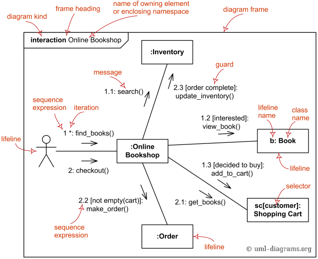
The major elements of UML communication diagram.
Frame
Communication diagrams could be shown within a rectangular frame with the name in a compartment in the upper left corner.
There is no specific long form name for communication diagrams heading types. The long form name interaction (used for interaction diagrams in general) could be used.
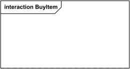
Interaction Frame for Communication Diagram BuyItem
There is also no specific short form name for communication diagrams. Short form name sd (which is used for interaction diagrams in general) could be used. This sd is bit confusing as it looks like abbreviation of sequence diagram.
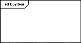
Sd Frame for Communication Diagram BuyItem
Lifeline
Lifeline is a specialization of named element which represents an individual participant in the interaction. While parts and structural features may have multiplicity greater than 1, lifelines represent only one interacting entity.
If the referenced connectable element is multivalued (i.e, has a multiplicity > 1), then the lifeline may have an expression (selector) that specifies which particular part is represented by this lifeline. If the selector is omitted, this means that an arbitrary representative of the multivalued connectable element is chosen.
A Lifeline is shown as a rectangle (corresponding to the "head" in sequence diagrams). Lifeline in sequence diagrams does have "tail" representing the line of lifewhereas "lifeline" in communication diagram has no line, just "head".
Information identifying the lifeline is displayed inside the rectangle in the following format:
lifeline-ident ::= ([ connectable-element-name [ '[' selector ']' ] ] [: class-name ] [decomposition] ) | 'self'
selector ::= expression
decomposition ::= ‘ref’ interaction-ident [ 'strict' ]
selector ::= expression
decomposition ::= ‘ref’ interaction-ident [ 'strict' ]
where class-name is type referenced by the represented connectable element. Note that, although the syntax allows it, lifeline-ident cannot be empty.
The lifeline head has a shape that is based on the classifier for the part that this lifeline represents. Usually the head is a white rectangle containing name of the class after colon.

Anonymous lifeline of class User.

Lifeline "data" of class Stock
![Lifeline x selected with [k] of class X. Lifeline x selected with [k] of class X.](https://www.uml-diagrams.org/notation/communication-lifeline-selector.png)
Lifeline "x" of class X is selected with selector [k].
If the name is the keyword self, then the lifeline represents the object of the classifier that encloses the Interaction that owns the Lifeline. Ports of the encloser may be shown separately even when self is included.
Message
Message in communication diagram is shown as a line with sequence expression and arrow above the line. The arrow indicates direction of the communication.

Instance of class A sends remove() message to instance of B if s1 is equal to s2
Sequence Expression
The sequence expression is a dot separated list of sequence terms followed by a colon (":") and message name after that:
sequence-expression ::= sequence-term '.' . . . ':' message-name
For example,
3b.2.2:m5
contains sequence expression 3b.2.2 and message name m5.
3b.2.2:m5
contains sequence expression 3b.2.2 and message name m5.
Each sequence term represents a level of procedural nesting within the overall interaction. Each sequence-term has the following syntax:
sequence-term ::= [ integer [ name ] ] [ recurrence ]
The integer represents the sequential order of the message within the next higher level of procedural calling (activation). Messages that differ in one integer term are sequential at that level of nesting.
For example,
- message with sequence 2 follows message with sequence 1,
- 2.1 follows 2
- 5.3 follows 5.2 within activation 5
- 1.2.4 follows message 1.2.3 within activation 1.2.
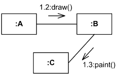
Instance of A sends draw() message to instance of B, and after that B sends paint() to C
The name represents a concurrent thread of control. Messages that differ in the final name are concurrent at that level of nesting.
For example,
- messages 2.3a and 2.3b are concurrent within activation 2.3,
- 1.1 follows 1a and 1b,
- 3a.2.1 and 3b.2.1 follow 3.2.
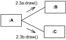
Instance of A sends draw() messages concurrently to instance of B and to instance of C
The recurrence defines conditional or iterative execution of zero or more messages that are executed depending on the specified condition.
recurrence ::= branch | loop
branch ::= '[' guard ']'
loop ::= '*' [ '||' ] [ '['iteration-clause ']' ]
branch ::= '[' guard ']'
loop ::= '*' [ '||' ] [ '['iteration-clause ']' ]
A guard specifies condition for the message to be sent (executed) at the given nesting depth. UML does not specify guard syntax, so it could be expressed in pseudocode, some programming language, or something else.
For example,
- 2.3b [x>y]: draw() - message draw() will be executed if x is greater than y,
- 1.1.1 [s1.equals(s2)]: remove() - message remove() will be executed if s1 equals s2.

Instance of class A will send message
draw() to the instance of C, if x > y
draw() to the instance of C, if x > y
An iteration specifies a sequence of messages at the given nesting depth. UML does not specify iteration-clause syntax, so it could be expressed in pseudocode, some programming language, or something else. Iteration clause may be omitted, in which case the iteration conditions are unspecified.
The * iteration notation specifies that the messages in the iteration will be executed sequentially. The *|| (star followed by a double vertical line) iteration notation specifies concurrent (parallel) execution of messages.
For example,
- 4.2c *[i=1..12]: search(t[i]) - search() will be executed 12 times, one after another
- 4.2c *||[i=1..12]: search(t[i]) - 12 search() messages will be sent concurrently,
- 2.2 *: notify() - message notify() will be repeated some unspecified number of times.

Instance of class A will send search() message to instance of B n times, one by one

Instance of class A will send n concurrent search() messages to instance of B
Recurrence is not repeated at inner levels in a nested control structure. Each level of structure specifies its own iteration within the enclosing context.
Comments
Post a Comment